|
|
MECH 200 Engineering Drawing
Lab 1: Basic AutoCAD 2-D Drawings
|

Objective
- To understand the fundamentals
of AutoCAD
- To use the basic editing
commands, menus, and save drawings.
- To create 2-D drawings for a
simple plate and a disc
Introduction & Concepts
AutoCAD is one of the more popular drafting packages around and is often
considered as the baseline skill for CAD Technicians and engineers. Students of
Engineering sometimes assume that CAD is a low-level task they do not require
any abilities in. This is a false assumption, since Engineers are often
required to produce schematics and illustrations to document their designs.
Reports and presentations are essential in the proposal of new ideas, and often
the Engineer does not have the luxury of a personal CAD Technician at this
stage of the project. As a result, those Engineers with CAD skills are the ones
whose ideas get approved for production.
As a student, you will find mastery of AutoCAD invaluable. You will get
more job interviews in the co-op process, produce superior project and
work-term reports, and be able to communicate your ideas more effectively with
a minimum of extra effort.
The History of AutoCAD
AutoCAD has been around almost as long as the Intel
8086 family of processors (almost 20 years now). The first versions of AutoCAD
were written to run on Personal Computers based on the ancient 286 processor.
On these first PC's memory was incredibly scarce by today's standards (under
640 kB) and disk drives were amazingly tiny (a 40 MegaByte hard drive was
considered massive, and floppy disks were actually floppy). These machines
sported the very first VGA display adapters, giving them a 640 x 400 graphics
screen mode in addition to their "blocks of characters" text mode.
In order to run on these primitive systems, these first versions of
AutoCAD were amazingly stingy with memory and drive space, and had none of the
graphical interface features such as the push-button icons, pull-down menus and
dialog boxes that users now take for granted. AutoCAD expected the user to type
drawing commands and answer questions on a command line while simultaneously
entering coordinates with the mouse. Everything was done this way, and users of
AutoCAD had to be quick typists with good memories to be effective.
Although times have changed since the primitive days of the eighties,
AutoCAD's way of doing things has not. As computers have gotten faster and more
sophisticated, AutoCAD has become fancier and more "Windows 95-like"
but it still demands typed commands and answers from its users according to the
same syntax it expected in 1986. In this way, people who learned how to use
Version 9 or earlier can get good results from current versions.
The AutoCAD Text Screen
Just as it did on DOS based 286 machines,
AutoCAD uses both a text screen and a graphics screen to interact with its
user: The text screen behaves exactly like a command line in DOS or a
terminal window in Unix, and is used by AutoCAD to record past commands
and their responses. Certain commands depend on this screen to list large
amounts of data, so don't think it's unimportant: There will be times in the
future when AutoCAD will trick you into thinking it has crashed when in fact it
is merely waiting for you to enter something in this screen. Don't
minimize this window into an icon... that's just asking for trouble!

Figure 1:
The AutoCAD Text Screen
The AutoCAD Graphics Screen
The graphics screen is where 98% of AutoCAD's business
gets done. In ancient times, the early versions of AutoCAD would toggle between
this screen and the text screen whenever the user pressed the F1 key on their
trusty 286. In the windowed environments we use today, this screen lives in its
own window, sometimes referred to as the drawing editor.
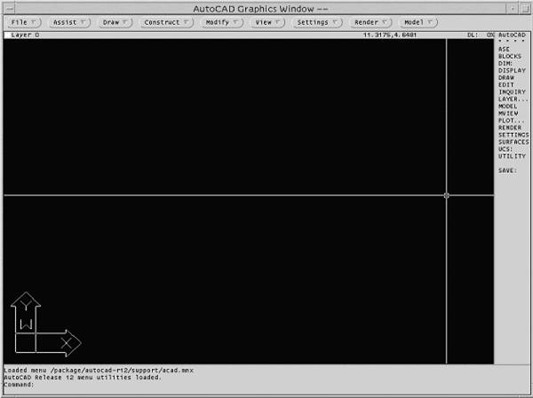
Figure 2: The AutoCAD Graphics Screen
The AutoCAD graphics screen is divided into four parts. To the right is
the Side Menu , at the bottom is the Command Line,
along the top is the Status bar, and the rest of the screen is
the Drawing Area. There are also pull-down program menus
above the status bar, but these are standard equipment on all windowed
operating system programs, so we won't get into them here.
The side menu displays your current command options. Long before
pull-down menus even existed, this was the only type of menu that AutoCAD
offered. The side menu is very effective at speeding up interaction between you
and AutoCAD. Mouse-clicking on any of the options currently listed has the same
effect as typing them on the command line. The command line itself is where you
enter commands for AutoCAD and answer its various questions. The status bar
displays current information about your drawing, and the drawing area is where
you create and edit your drawings using the mouse.
Interacting with AutoCAD
Most people with computer experience are familiar with
pull-down menus. After all, every Microsoft Windows, Macintosh, and X-Windows
programs uses them. As a result, you might be tempted to use AutoCAD's
pull-downs in the same manner and ignore the side menu and command line to save
yourself some hassle... Don't do that: It will cause you more
trouble than it saves.
AutoCAD's entire way of thinking revolves around the
command line concept. You give AutoCAD a command, and it asks you a series of
questions regarding the command. When all the questions are answered, AutoCAD
completes the command. This approach doesn't mesh well with pull-down
menus for anything other than simple operations, so it is recommended you bite
the bullet and learn the command line way before you start drawing with
AutoCAD's pull-down menus.
AutoCAD informs you it is ready for instructions with the following
command line prompt:
command:
After you have typed a command and hit the <Enter> key, you will
see the command line scroll one line up and display a new prompt asking you for
any new information required by the current command. The side menu will also
change at this point to show the subcommands and options available to you:
Clicking on any of these side menu items will automatically enter them at the
new command line prompt. Once you have answered the question, AutoCAD will
either prompt you for more information or complete the command if no more
interaction is required.
A Command Example
Now we'll look
at a simple example of command line interaction: Let's draw a line:
AutoCAD says...
command:
You type in the line command...
command: line
After you hit the <Enter> key, AutoCAD asks for the first point of
the line...
command: line
From point:
You answer by typing in a 2-dimensional coordinate (2,3). We could pick
the point by clicking the mouse in the drawing area, but let's keep things on
the command line for simplicity's sake.
command: line
From point: 2,3
(Do you notice how brackets around the coordinates aren't required on the
command line?)
AutoCAD now asks for the second point of the line. You type in
coordinates (6,7)...
command: line
From point: 2,3
To point: 6,7
AutoCAD now asks for the third point of the line. You could type in as
many coordinates as you want in the line, repeating the last interaction as
many times as necessary. For the sake of argument though, let's say two points
is all you require. Simply hit the <Enter> key at the "To point:" prompt.
command: line
From point: 2,3
To point: 6,7
To point: (Hit
<Enter> here, rather than type in any more coordinates...)
To AutoCAD, you are refusing to answer the question by hitting
<Enter> at this point, so it assumes the command is done. AutoCAD now
prompts you for the next command as follows...
command:
Canceling a Command
There is bound to come a time when you start the wrong
command by mistake. To cancel a command in progress, simply hit the <Ctrl
> and < c > keys together: AutoCAD will drop whatever it's doing
and return to the "Command:"
prompt.
Command Aliases
We all know that Engineers hate to type (proper
spelling is often required). Command aliases are abbreviations that AutoCAD
understands when they are typed at the command line. Some of the favorite ones
are:
u
undo
e erase
r redraw
z zoom
m move
There are many more than those listed above. Experiment by typing the first
letter of any command you wish to execute. Over the course of a drafting
session, you will be amazed at how much time and hassle these aliases can save
you!
Command Line Options and Defaults
As you will see over the next few months, some of
AutoCAD's commands have many steps from start to completion. AutoCAD uses a command
line syntax remind you of the subcommands currently availiable, as well as the
default subcommand that will be selected if you hit <Enter> without
making a choice.
AutoCAD's Inner Universe
Right now, you probably think of AutoCAD's drawing
area as a flat surface of fixed dimensions where you draw pictures - It's
actually a window into a virtual 3D universe of incredible size and resolution
where you can create not only drawings, but three dimensional models of great
scope and detail.
AutoCAD uses single precision floating point numbers to define the
coordinates of its universe: The numerical value of these coordinates can be
from -1038 to 1038 (approximately), and the
resolution between two consecutive numbers in this range is approximately 10-38.
The resulting scope and resolution of the universe accessible through the
drawing area is truly mind-boggling if you think about it.
The Coordinate System
The lab manual will tell you that AutoCAD uses a
rectangular cartesian coordinate system with the X axis running horizontally
across the screen and the Y axis increasing vertically toward the top of the
screen. This is a simplification made to help you get started quickly without
too much deep thought or worries.
In actual fact, AutoCAD's coordinates system is fully 3D, with a Z axis
that is related to the X and Y axes by the right-hand rule: When
you use your right hand to rotate the X axis into the Y axis (The heel of your
hand stays fixed at coordinates (0,0,0)), your thumb will point in the positive
Z axis direction.
Imagine that you are in a virtual spacecraft, and the viewscreen is none
other than the AutoCAD drawing area. You are free to pilot anywhere in
AutoCAD's universe, rotating your ship to look in any direction. As you might
guess, your ship would get lost pretty fast if it didn't have some sort of
guidance system built in. This 3D virtual compass is called the UCS Icon.
Figure 3: The UCS Icon
UCS stands for User Coordinate System, and this Icon is
always shown at the bottom left-hand corner of the drawing area. It gives you a
clear indication how your view lines up with the AutoCAD's coordinate system.
For simple two dimensional drawing purposes, it makes sense to have your view
oriented as described in the lab manual, with the X axis running horizontally
across the screen and the Y axis increasing vertically toward the top of the
screen.
Figure 4: Four views of your Virtual Spacecraft in
AutoCAD's Universe
The figures above demonstrate the best way to visualize the relationship
between the AutoCAD drawing area and the virtual universe inside each drawing
you create. You are aboard the spacecraft and the drawing editor is your
viewscreen. You can adjust the magnification of this viewscreen to include as
much or as little of this universe as you see fit, and (in later labs) you can
move and rotate your ship around this universe to create three dimensional
views of your drawings.
Now that you know AutoCAD's universe is fully 3D, you can safely ignore
the Z Axis. As long as our virtual spacecraft stays oriented as shown above,
everything will appear and behave two dimensional. If no Z coordinate is
supplied when you enter points at the command line, AutoCAD will assume Z = 0,
and mouse-picked points will always have a Z coordinate of zero from this
virtual viewpoint.
Redefining
the Limits of AutoCAD's Universe
People use AutoCAD to draw from circuits to
skyscrapers and beyond. It follows that different drawing files require
different sized regions of AutoCAD's virtual universe to accomodate the objects
they depict. As the user, you are expected to set these regions yourself for
each drawing file you create. This
process is called setting the drawing's limits and it should be
done before you draw anything in a new AutoCAD file. Set your drawing's
limits with the limits
command. Choose limits large enough to fit everything you want to draw. AutoCAD
will then prompt you for the lower left hand corner limit (keep this at 0, 0)
followed by the upper right hand corner limit.
You'll need to use the zoom all
command after you redefine the limits in order to change your screen
magnification to match your new limits. To AutoCAD, "All" means to
adjust the zoom factor to include everything within the drawing file within the
drawing area, or to zoom to fit the current limits if nothing goes beyond their
rectangular boundary.
Creating a
Grid
Once your limits are set, you will need to define a
grid within them. This is accomplished with the grid command. This command asks you for a numerical value
which it uses to define the grid spacing. The grid is a matrix of points that
covers the defined limits. The grid will not extend beyond the limits, so take
care not to draw anything outside of its boundaries (any drawing entities
placed outside of the limits will not print to hard copy). Many drawing
programs that use grids have a "snap to grid" option that only allows
the user to only mouse-pick points that are also grid points. Be careful!
AutoCAD's grid has no effect on the selection of points like this. It is only a
visual tool.
Once defined, your grid can be toggled on and off with
the F3 key. Note that if you zoom too far out or define your grid too
densely for the current magnification, it won't be displayed: Use a different
grid spacing if this happens.
How to Mouse-Pick with Precision
Since the resolution of AutoCAD's coordinate system is
unbelievably high (10-38 is a decimal place with 38 zeros and a one
after it), the probability of correctly mouse-picking a desired point is
practically zero. This high resolution can therefore cause inaccuracies and
errors in your drawings if you mouse-pick your points while staring at the
coordinate display in the graphics window's status bar: This practice is called
eyeballing, and it is to be avoided at all times!
If you employ the techniques described in this section, you will learn
to use this resolution to your advantage. Remember that technical drawings must
be 100% accurate to be of any use, and that a sloppy drawing's innacuracies
will always cause trouble and eventual loss of employment in the real world...
Defining a
Snap
The most
obvious tool AutoCAD offers for precision mouse-picking is called the Snap
Mode. Think of the snap as an invisible user defined grid that can be
toggled on and off as required. When the snap is on, you may only mouse-pick
points that lie on this invisible grid. When the snap is off, the full
resolution of AutoCAD is applied to mouse-picked points. The snap is defined with the snap command. AutoCAD will prompt you
for a numerical value which it uses to space the points of the invisible snap.
Once defined, your snap can be toggled on and off with the F3 key. A
good rule of thumb is to define your snap and grid so that the grid spacing is
5 or 10 times that of the snap spacing. This will give you a visible grid with
five or ten invisible snap points in the space between its visible points.
Using The @ Symbol and Polar Point
Notation
Consider the following situation: You are drawing a
rectangular plate that is 23.4537 units tall and 17.2 units wide. You have
started drawing the line that depicts the left side of the plate. The lower
left-hand corner of the plate (the first point of your line, and the last point
you have entered) is at coordinate (13.25, 19.131).

Figure 5: Drawing the Side of the Rectangular Plate
In order to complete the side of this plate, you must
work out the coordinates of the top left hand corner by adding 25.4537 to the Y
coordinate of the last point you entered (19.131). Should you do this calculation
in your head, work it out on paper, or do you use a calculator?
Thanks to the success of the word-wide web, everyone
knows about the @ symbol. In AutoCAD, this symbol is a quick way to reference
the last point you have entered. In the situation above, the last point you
entered was the lower left hand corner of the plate (13.25, 19.131). By simply
typing "@" on the command line, you reference this point and its
coordinates as components for the next point's calculation. We know the next
point required is 25.4537 units directly up the Y Axis from our last point.
AutoCAD can calculate this for us if we use polar point notation as well as the
@ symbol as follows:
@25.4537<90
If you are having problems understanding this last
paragraph, think of it this way. The @ symbol reminds AutoCAD of the last point
entered. Next we give a distance (25.4537) and a direction (90 degrees),
separated by the lesser-than symbol "<" which is AutoCAD's substitute for an angle
symbol.
After entering @25.4537<90, we find that @ now refers to the upper
left hand corner...we are therefore free to continue using polar point notation
to draw the top of the plate with a line to the upper right hand corner:
@17.2<0
Using The
OSnap Tools
As your draw new objects, the object database within
your drawing file will expand to store them. This internal database is how
AutoCAD keeps track of everything that exists in its virtual space, and is
available when you mouse-pick points if you know how to use the OSnap modes.
OSnap is an abbreviation of Object Snap:
It's a way to mouse-pick points that are part of objects you have already
drawn. If you need to pick the center of a circle, the end of a line, or the
tangent point of an arc, all you need to do is use the appropriate osnap just
before mouse-picking a point in the general area of the object's feature of
interest.
Click the right mouse button when the cross-hairs are
within the drawing area to call up the OSnap pop-up menu. Of the available
osnap tools, the following are relevant to the beginner:
Center cen
This osnap returns the center-point of any circle selected. Remember you pick a
circle by mouse-picking a point along its circumference, not within its
interior!
Endpoint end
This osnap returns the end-point of any line or arc selected. The end-point
selected will be the closest to the point you actually mouse-pick.
Intersection int
This osnap returns the intersection of any two objects. Mouse-pick the
intersection as close as possible to give the osnap a good starting point to
search from. Don't use this one if osnap endpoint will do, it's more accurate.
Midpoint mid
This osnap returns the mid-point of any line selected.
Nearest near
This osnap returns ANY point on the object selected. You won't use it often.
Perpendicular perp
This osnap finds the point along any selected line entity required to make a 90
degree angle with the last point entered. Experiment to get a better idea on
how this works...
Quadrant quad
This osnap returns the closest quadrant point of any circle selected. The
quadrant points of a circle are located on the circumference at bearings 0, 90,
180, and 270 degrees.
Tangent tan
This osnap finds the point along any selected arc or circle required to draw a
tangent line from the last point entered. Experiment to get a better idea on
how this works...
None none
This osnap turns off any currently set osnap mode. More on these in the next
section...
Setting OSnap Modes
The Osnap tools shown above work as one-shot commands
that apply only to the next mouse-picked point. To make any of these tools the
default mouse-picking mode, you need to run the osnap command and select any one of the osnap tools. This osnap tool will be
used EVERY TIME you mouse-pick unless you override it with another osnap (using the
pop-up menu described above), or run the osnap command again to change the mode back to none.
Using Osnaps
and Polar Notation to create Construction Geometry
There will be many times when you will draw temporary
lines and circles whose only purpose is to serve as the basis for final
objects. These objects are called Construction Geometry, and they
serve a similar purpose to the scaffolding used by real-life construction crews
raising a building. To get an idea of how osnap, polar notation and construction geometry can work
together in your drawings, consider the following situation:
This lab asks you to draw a 30 x 20 rectangular tab, centered around a
circle of radius 5 at point (55,50). Drawing the circle is easy enough, you
enter the centerpoint and radius and it's done.
Likewise, drawing the tab is also easy if you use polar notation: run
the line command and
pick any nearby point, followed by @30<180, @20<270, @30<0, and then close to complete
the tab.
Here's the tricky part - Centering the tab around the circle. First, you
draw a horizontal line (which is construction geometry, by the way) 30 units
long and move it so that its midpoint is positioned on the center of the circle:
Start the move
command and then
- Pick the line and hit <Enter> to
select the line for moving,
- type mid, and
pick the line again to specify the base point of the move, and then
- type cen, and
pick the circle to specify the second point of displacement.
Now you can move the whole tab so that the midpoint of
one of its sides coincides with the endpoint of the construction line: Start
the move command and
then
- Select all of the lines that make up the tab and
hit <Enter> to select them for moving,
- type mid, and
pick either of the vertical sides of the tab to specify the base point of
the move, and then
- type end, and
pick the corresponding end of the construction line to specify the second
point of displacement.
You can now erase the construction line, because it
has served its purpose!
Chamfers
& Fillets
Examine your computer desk. Chances are the desktop
has rounded or blunted corners to stop anyone from bruising themselves on a
sharp edge. The two techniques used in manufacturing to achieve this effect are
Chamfering and Filleting.
Chamfering
Chamfering is an operation whereby the sharp corner is
effectively flattened by trimming it off with a linear cut:
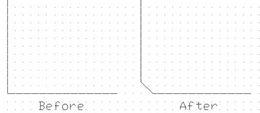
Figure 6: A Chamfered Corner
You can chamfer any corner in your AutoCAD drawing
with the chamfer command. This command prompts you to choose the lines
that make up the corner, and then for the x and y distances from the
corner to place the ends of the chamfer cut.
Filleting
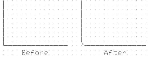
Figure 7: A Filleted Corner
Filleting is an operation that rounds a sharp corner
into an arc of arbitrary radius: This is achieved in AutoCAD with the fillet command. This
command has two modes of operation: The first mode allows you to set the fillet
radius, while the second prompts you to choose the lines that make up the
corner to be filleted. This second mode will continue to prompt you for corners
to fillet until you press Esc or Enter.
Arrays
AutoCAD's array command is designed to create armies of clones from a
single selection of objects. How these copies are placed relative to the
original depends entirely on whether you choose the rectangular
or polar options.
A rectangular array is defined by a horizontal and vertical cell spacing
between members, while a polar array is defined by a radial and angular cell
spacing about a common centerpoint. To create a polar array of eight objects
around a common centerpoint, you must
- Select the original object to copy,
- Specify a polar array,
- Pick the centerpoint of the array,
- Enter the number of objects in the final array
(eight in this case),
- Specify the angular sweep covered by the array
(full circle equals 360 degrees), and
- Indicate if you want the objects rotated as they
are copied.
Linetypes
AutoCAD's way of handling different linetypes is quite
different to that of any other graphics program you might have experienced
before. Linetype definitions must be loaded into any drawing before they may be
used: This saves a little bit of memory for AutoCAD and reduces the size of
your drawing file (not too essential today, but it meant a lot in the days of
the 286 PC). Linetypes are loaded with the linetype command.
Once loaded, you will want to adjust the scale factor
of your linetypes. This is a global variable called ltscale that can be
any positive number. Redefine this variable to change the spacing of your
lineteypes, but be careful, since it governs every linetype in your drawing.
One way to change your linetype spacing while avoiding
the ltscale variable is to use the 2 and X2 variations of your desired linetype.
For example, the linetype dashed has a variation called dashed2
that is twice as dense, and a variation called dashedX2 that is
twice as sparse. This naming convention holds true for all the linetypes you
might wish to use.
Figure 8: The 2 and X2 Linetypes
Blipmode
As you mouse-pick points in AutoCAD you will notice
tiny cross-hair markers being left behind. Eventually, your screen will be
covered with the remains of these "blips", and the appearance will
not be unlike specks of dirt left all over your drawing. Most people hate this
effect and would turn it off if they could. Fortunately, this is easily
achieved by changing the blipmode
variable to OFF. After this has been done, no more blips will be drawn,
although the existing specks will remain until you command AutoCAD to redraw
the screen.
Redraw and
Regenerate
On occasion you will find your AutoCAD screen getting
"dirty" with half deleted lines and negative images from moved and
erased entities. The quickest cure for this is the redraw command,
which refreshed the display from AutoCAD's video buffer. Occasionally, even a
redraw is not sufficient to clear up some display problems, and so you will
find that the regenerate
command is required. The regenerate command actually rebuilds the video buffer
from AutoCAD's object database, and is guaranteed to fix any corruption of the
display.
Lock Files and Drawing Filename
Extensions
The version of AutoCAD running on the University lab
workstations is a shared program. There can be up to 50 people using it at any
one time, and therefore certain problems can arise that aren't possible on a
desktop computer.
Imagine you and a partner are working on a drawing project. Each of you
are responsible for drawing different parts of the same drawing, and you
usually take turns working on it. Late one night, you decide to log in and get
some work done... Unfortunately, unknown to you, your partner has also logged
in before you and is making all kinds of progress of her own. From the moment
you open the drawing file, a bizarre game of tennis begins. She saves her work,
you save your work, she saves her work, and so on... Whoever saves their work
last wins the game. The loser will have to do everything all over again!
The horrifying scenario above is not possible because AutoCAD implements
a feature known as file locking. When you open a drawing file
(i.e. lab1.dwg), AutoCAD creates a lock file to safeguard the drawing
file (in this example it would be called lab1.dwk). As long as the
lock file exists, AutoCAD will refuse to load the drawing for editing by anyone
else, thereby avoiding the nightmarish situation above. Whenever you finish
editing a drawing and exit AutoCAD, the lock file is deleted, and anyone with
access to the drawing file can once again open it for editing.
Although file locking prevents the above problem (sometimes referred to
as version-itis), a problem does arise whenever AutoCAD crashes
in the middle of editing a file. The lock file is not deleted in
the crash, and you consequently get locked out of your own drawing! The next
time you try to edit your drawing, AutoCAD will see the lock file and think
someone else is currently using the drawing file: You'll be denied access to
your drawing unless you get rid of the lock file yourself.
To remove a lock file, you must go to a terminal window such as the pulley
shell window you will find on your workstation's desktop. Simply change
to the directory where your drawing file is located and delete the file with
the .dwk extension and the same name as your drawing. Do
not delete the .dwg file by accident: It is your drawing file!!!
In UNIX, you change directories with the cd
command, list their contents with the ls
command, copy files with the cp command, and
delete files with the rm command
To recap the drawing extensions that AutoCAD uses, we consider a drawing
called monster.
AutoCAD will create three files to support this drawing:
- monster.dwg This is the actual drawing file: It contains all
your work to the last save.
- monster.bak This is the backup of the drawing file: It
contains all your work to the 2nd last save.
- monster.dwk This is the lock file: It
exists only when you are editing the drawing.
Procedures
Creating the Plate
- Save the drawing as plate. AutoCAD
will automatically add the .dwg extension to your filename.
- Examine the Plate Specification Drawing and set
the drawing limits to comfortably fit what you are about to draw
with the limits command)
- Set the grid to a spacing of 5 with the grid command.
- The default limits for AutoCAD is 12 x 9, which
you reset in step 2. Zoom the magnification of the drawing area to
encompass your new limits and grid with the zoom all command.
- Set the snap mode to a spacing of 1 (integer
values only): Use the snap command.
- Refer to the Plate Specification and draw the
rectangular outer boundary connecting points A to B,
B to C, C to D and
D to A. Leave the corners of the plate sharp
and unchamfered for now.
- Use the circle
command to create the circles concentric around point E.
repeat this command to create the lower left-hand circle centered on point
F. Note that the
 symbol means "diameter" in the Plate
Specification.
symbol means "diameter" in the Plate
Specification.
- Draw the lower left-hand rectangular tab around
point F. You can avoid mental coordinate calculations by using the osnap modes, polar notation and construction geometry.
- Fillet the rectangular tab with a radius of 3.
Use the fillet command.
- Copy the tab and circle from base point F
to multiple second points G, H and I.
Use the copy command with the multiple option.
- Draw a construction line joining the 0 degree
quadrants of the concentric circles about point E. Use osnap quad to achieve this in one command. Next, draw a
circle of radius 7 whose centerpoint is also the midpoint of this construction
line (hint: use osnap mid). Finally, erase the
construction line.
- Use the array
command to create a polar array of eight circles from the one you just
drew.
- Run the chamfer
command and set the first and second chamfer distances to 10. Repeat the
command and pick the corners of the plate to chamfer each of them
automatically.
- Use the offset command to set the offset distance to 10. Now
repeat the command and offset the outer edge of the plate (including the
chamfers) to create the inner boundary line (consult the Plate
Specification Drawing for details if this sounds
confusing). These offset generated lines will overlap, but don't worry.
You'll fix them in the next step.
- Trim off the unwanted ends of the offset lines
with the trim command: This command asks you
to select objects that will act as cutting edges, and then to select the
ends of the objects to trim. Try it out - it's easy, although you will
have to run the command twice to get the desired effect: Once to trim the
chamfer offsets to the right length, and a second time to trim off the
unwanted vertical and horizontal line ends.
Creating the Disk
- Open a New drawing and save it as disk.
AutoCAD will automatically add the .dwg extension to your filename.
- Examine the Disk Specification Drawing and set
the drawing limits to comfortably fit what you are about to draw
with the limits command. Make the limits as
tall as they are wide, and choose even numbers for the upper-right
coordinate: (200,200) for example.
- Set the grid to a spacing of 5 with the grid command.
- The default limits for AutoCAD is 12 x 9, which
you reset in step 2. Zoom the magnification of the drawing area to
encompass your new limits and grid with the zoom all command.
- Set the snap mode to a spacing of 1 (integer
values only): Use the snap command.
- Refer to the Plate Specification and draw the
three concentric circles that define the disk's inner diameter 92 and outer radii R75 and R90. Choose the
centerpoint to be one half of the upper-right coordinate: (100,100) for
example. Hint - After you have entered this value the first
time, you can refer to it by typing the @ symbol
on the command line when prompted during the next two runs of the circle command.
- Draw a construction line from the 0 degree
quadrant point (see osnap quad for details) to the
centerpoint of the circle, and then use the rotate command to rotate this line by +15 degrees about
the centerpoint.
- Create a horizontal mirror image of the
construction line with the mirror
command: The mirror line should go from the centerpoint of the circle to
the 0 degree quadrant: Do not agree to delete the original line when asked
by AutoCAD, because you still need it.
- Run the array
command and create a polar array from your two construction lines. You
want 4 items, swept over 360 degrees, rotated as they are copied.
- Draw a circle with diameter 14, centered on the 0
degree quadrant of the R75 circle; Rotate it +30 degrees around the disk's
centerpoint.
- Repeat the last step but rotate the circle +60
degrees about the disk's centerpoint this time.
- Run the array
command and create a polar array from the two new rotated circles. You
want 4 items, swept over 360 degrees, rotated as they are copied.
- Draw a line from the 0 degree quadrant of the R90
circle to its 180 degree quadrant . This will be the horizontal centerline
notation when we are done. Now draw a line from the 90 degree quadrant of
the R90 circle to the 270 degree quadrant: This will become the vertical
centerline notation in time.
- Run the linetype
command: AutoCAD will ask you which linetype to load from the acad.lin
file. load the center linetype.
- Change the linetype property of the vertical and
horizontal centerline by running the chprop
command: You must select both lines, and then change their ltype from BYLAYER to center.
- You will likely not see any difference in the
centerlines after the previous step: This is because the drawing's ltscale
variable is set too low: Type ltscale at the
command line to set this variable to a larger value (15, for example).
- Now you can trim away all the unwanted lines from
your disk drawing. Refer to the Disk Specification Drawing
for details, and be careful! Remember you can always use the undo command if you make a mistake.
Deliverables
·
In this lab you will be producing two drawings in
AutoCAD which are shown in the Specification Viewer.
1. Plate
2-D drawing and
2.
Disk 2-D drawing
·
A single top view drawing of each object is sufficient
to specify the details.